DRO Mount (Y-axis) on Sieg SX3
There are many posts about DRO installation on a bench top mill. This is yet another one.
This post details how I installed DRO on the Y-axis of my Sieg SX3. Unlike most other builds I've seen, I elected to use magnetic tape, instead of the usual plunger- or optical scales.
Magnetic tape and encoder has several advantages over optical scales (which in turn are better than plungers):
- The magnetic tape mounted in an aluminium profile is much more robust than an optical scale
- Both scale and encoder head are fully sealed to IP67 which makes them much more resilient to the harsh environment on a mill
- The required aluminium profile and magnetic encoder head are much smaller than a comparable optical system, making them easer to fit in tight spaces
Since I live in Denmark, the selection of readily available DRO systems is much smaller than in the states. I selected a system from Allendale Electronics Ltd., and they provided excellent support on selecting suitable components for my specific mill.
Of course this comes at a price, and a full DRO system using magnetic tape and encoders is around 20% more expensive than a comparable system using optical scales. Also, while the magnetic encoders have a resolution of 1 micron (0.001mm), their accuracy is only +/- 0.015mm whereas typical optical encoders have an accuracy of +/- 0.005mm, and this may be a deal breaker for some.
I doubt the Sieg SX3 is capable of repeatedly working to such tolerances, and the temperature variations in my workshop are certainly much too great for that level of accuracy. Also, the prototypes I make usually only need to hold "look good" tolerances, typically within 0.08-0.1mm. So, I prioritised the practical benefits of a system based on magnetic encoders, and I've been very happy with it so far.
Installation
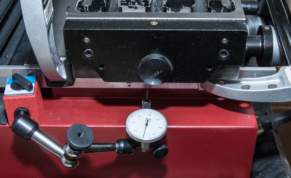
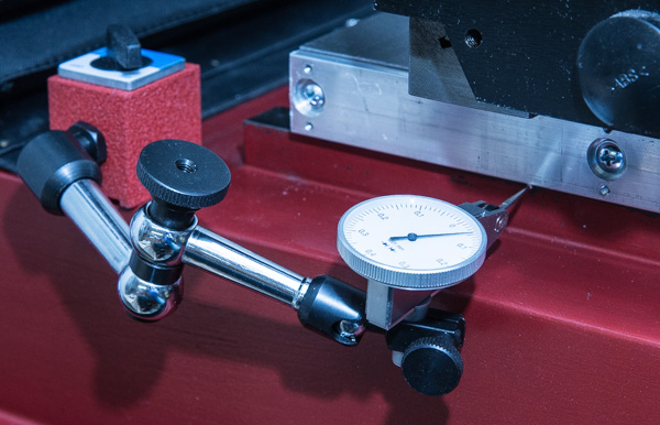
Using a dial indicator to level the aluminium profile holding the magnetic tape.
The mounting holes in the aluminium profile was used to transfer the hole locations to the Y-axis saddle. The holes in the aluminium profile has recessed hole for the screw heads. The OD of a 13mm hole transfer punch fits perfectly in this recess.
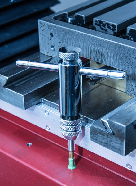
The transferred holes are then drilled to Ø3.2mm.
The drilled holes are tapped with an M4 tap. There was no room for a tap guide, and an M4 tap is easy to snap, so I used a new taps, separate rougher, intermediate, and finisher taps, and plenty of cutting paste to prevent tap breakage. The Y-axis saddle is cast iron which is actually very easy to tap, and yields very clean and well defined threads.
This is a test mount to check for fit of the aluminium profile. As can be seen, it has not been cut to size yet. The extrusion is mounted with M4 screws, but the pre-cut holes in the profile are Ø6mm, so they allow for plenty of play to compensate for off-centre mounting holes, and any fine adjustments to level the extrusion.
I used the Y-axis saddle as guide to scribe lines where the profile will be cut to length.
After the profile is cut to length, the dial indicator setup is again used to level the profile on the Y-axis saddle.
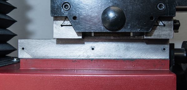
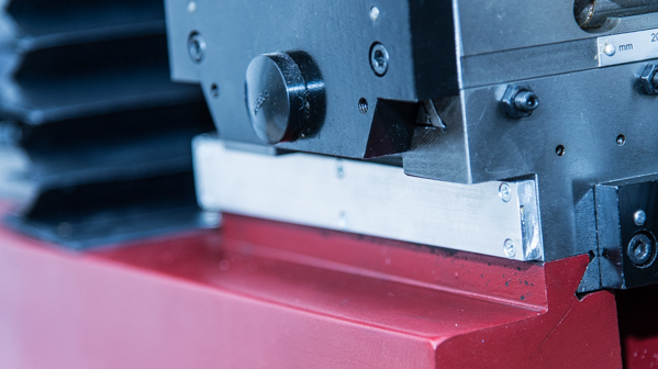
The profile mounted with cover holding the magnetic tape.
Next, a bracket is made, that will hold the magnetic encoder head. It is just a simple aluminium angle bracket with 4 holes. Two for mounting to the mill base, and two for holding the encoder head.
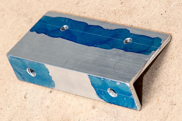
The bracket was used to again transfer the hole locations to the mill base using a hole punch. The angle bracket does not provide a very good guide for the hole punch, so afterwards it was necessary to shape the mounting holes in the bracket with a needle file. Slightly annoying, but it has no practical implications.
After the holes were transferred they were drilled with Ø4.3mm and tapped using M5 rougher, intermediate, and finisher taps. The mill base cast is only about 12mm thick, so it was an easy through-hole tap, even though there wasn't room for a tapping guide.
In retrospect, I could easily have used a finisher tap directly, since the cast iron is very easy to cut, and a broken tap would have been easy to remove. However, I approach all modifications I make on existing (=expensive) equipment as one-shot-only, and so I take the long approach of tap forming.
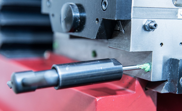
Here, the bracket is mounted and the magnetic encoder head is installed on the bracket. Clearance between the encoder head and the profile must be between 0.1-1.00mm, so I used a 0.5mm feeler gauge to set the distance.
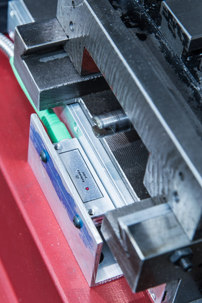
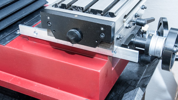
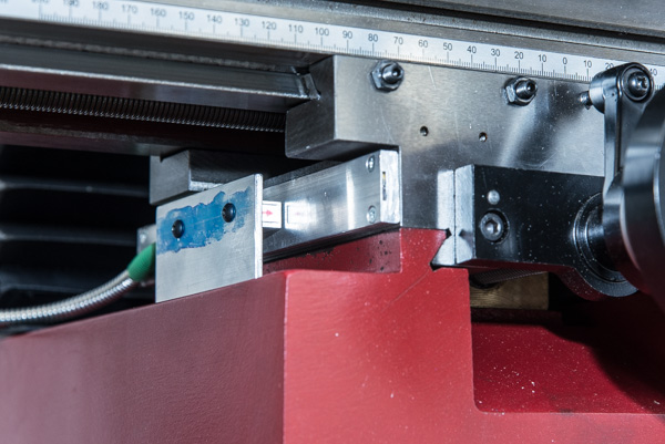
A different view of the final installation. I find that the magnetic tape and encoder gives a very clean and tight installation. It avoids the extensive angle bracket and mounting on the side of the mill base, and it employes the mill table as a natural chip shield.
The magnetic tape is impervious to coolant and chips, and the encoder head itself is protected to IP67 so in principal, a chip shield is not necessary. However, I think that chips could easily get stuck in the tight clearance between the encoder head and profile holding the magnetic tape, and so I believe that a chip shield is still necessary.
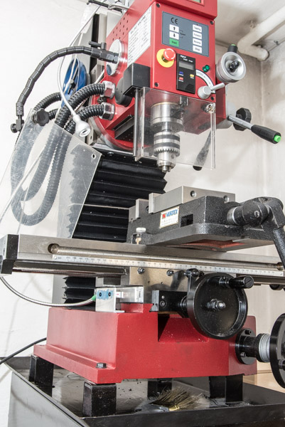
And this is what the full thing looks like :-)
blog comments powered by Disqus
Published
Tags
Related Posts
- DRO Mount (X-axis) on Sieg SX3
- Choosing A Mill
- Awesome, Inexpensive, Machine Tool Light
- Z-axis Bellows Mount (Part 2): Top Bracket
- New Lathe, The Wabeco D4000E